
Task Objective
The main objective of this group task was to control the motion of a DC motor making it move forwards, backwards, and stop with the aid of sensors and switches only without using neither push buttons nor any line of code. Therefore, the task was focused on controlling the motor's motion using pure electronics in order to better understand the concepts of electronics and the functions of the different components. We worked as a group of four members.

Transistor as a Switch
Transistors are commonly used in digital circuits as electronic switches which can be either in an "on" or "off" state, both for high-power applications such as switched-mode power supplies and for low-power applications such as logic gates. Important parameters for this application include the current switched, the voltage handled, and the switching speed, characterized by the rise and fall times.
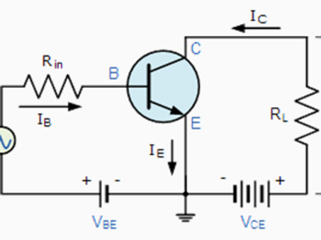
In a grounded-emitter transistor circuit, such as the light-switch circuit shown in the figure below, as the base voltage rises, the emitter and collector currents rise exponentially. The collector voltage drops because of reduced resistance from collector to emitter. If the voltage difference between the collector and emitter were zero (or near zero), the collector current would be limited only by the load resistance (light bulb) and the supply voltage. This is called saturation because current is flowing from collector to emitter freely. When saturated, the switch is said to be on.

Providing sufficient base drive current is a key problem in the use of bipolar transistors as switches. The transistor provides current gain, allowing a relatively large current in the collector to be switched by a much smaller current into the base terminal. The ratio of these currents varies depending on the type of transistor, and even for a particular type, varies depending on the collector current. In the example light-switch circuit shown, the resistor is chosen to provide enough base current to ensure the transistor will be saturated.
In a switching circuit, the idea is to simulate, as near as possible, the ideal switch having the properties of open circuit when off, short circuit when on, and an instantaneous transition between the two states. Parameters are chosen such that the "off" output is limited to leakage currents too small to affect connected circuitry; the resistance of the transistor in the "on" state is too small to affect circuitry; and the transition between the two states is fast enough not to have a detrimental effect.
Transistor as an Amplifier
The common-emitter amplifier, shown in the figure below, is designed so that a small change in voltage (Vin) changes the small current through the base of the transistor; the transistor's current amplification combined with the properties of the circuit means that small swings in Vin produce large changes in Vout.
Various configurations of single transistor amplifier are possible, with some providing current gain, some voltage gain, and some both. From mobile phones to televisions, vast numbers of products include amplifiers for sound reproduction, radio transmission, and signal processing. The first discrete-transistor audio amplifiers barely supplied a few hundred mill watts, but power and audio fidelity gradually increased as better transistors became available and amplifier architecture evolved. Modern transistor audio amplifiers of up to a few hundred watts are common and relatively inexpensive.
Steps of making our circuit
Now that we have introduced our components, lets discuss and show in details the exact steps that we went through to accomplish our group task. The task was divided into three main and consecutive steps which included:
(a) Working on the circuit design,
(b) Making the circuit design and PCB board on EAGLE, and
(c) Implementing the circuit in hardware.
a) Working on the circuit design:
In this first step, we come up with the idea of our circuit design by simply free-hand sketching our circuit along with all the required components that we will be using and the necessary connections between them as shown in the figure below. The circuit connections will be discussed in more details later in this section.
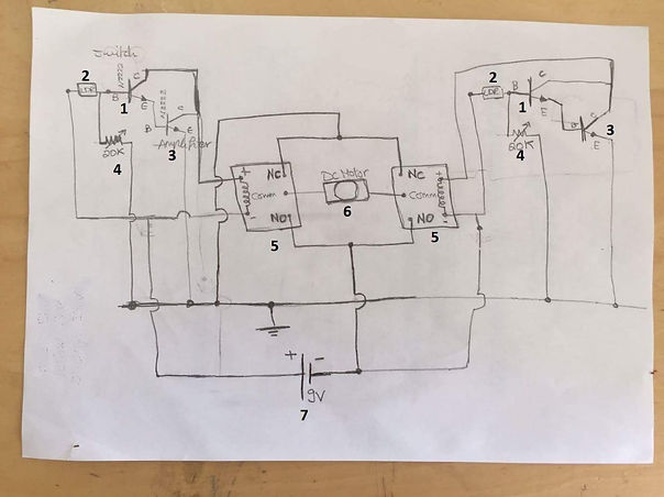
Here is a table showing all the required components along with their assigned numbers on the figure above, their functions, and the quantity of each component that we used.

And here is also a detailed bulleted list of all the connections for each component in the circuit.
Connections:
-
Transistor 2N2222: this acts as the switch transistor; we have two of them and each has three legs (Ct - Bt - Et), the collector (Ct) to which the load is connected, which in this case are the relays as they are connected to the actual load (DC motor), so it connects to the relay's first coil end (coil end 1) to provide the input signal originally coming from the LDR sensor in addition to being connected to the amplifier transistor's collector (Ca) too, the base (Bt) is connected to both the LDR sensor and the potentiometer, and the emitter (Et) is connected to the amplifier transistor's base (Ba).
-
LDR Sensor: we have two of them and each has two terminals, one is connected to the Vcc (5V) while the other is connected to the switch transistor's base (Bt).
-
Transistor BC547: this acts as the amplifier transistor; we have two of them and each also has three legs (Ca - Ba - Ea), the collector (Ca) also connects to the relay's first coil end (coil end 1) to amplify the input signal originally coming from the LDR sensor in addition to being connected to the switch transistor's collector (Ct) too, the base (Ba) is connected to switch transistor's emitter (Et), and the emitter (Ea) is directly connected to the ground.
-
Potentiometer B10k: we have two of them and each also has three legs, one of the side legs is connected to the switch transistor's base (Bt) and the middle leg is directly connected to the ground.
-
Relays: we have two of them and each has five legs (NO - NC - C - coil end 1- coil end 2), the normally open (NO) switch legs in the two relays are both connected to each other with a common junction/ node connected to the Vcc (5V), the normally closed(NC) switch legs in the two relays are also both connected to each other but with a common junction/ node connected to the ground, the common (C) legs in both relays are connected to the two motor terminals, the first coil end (coil end 1) in both relays is connected to both the switch transistor's collector (Ct) and the amplifier transistor's collector (Ca) at the same time, and finally the second coil end (coil end 2) in both relays is directly connected to the Vcc (5V). (Note: There must be a potential difference between the two ends of a relay's coil so that current would flow in the coil magnetizing it in order for the relay to latch properly.)
-
DC Motor: as discussed in the relays' connections, the motor has its two terminals connected to the commons (C) of the relays.
-
9V Battery: its positive terminal is connected to the positive Vcc line of the breadboard and its negative terminal is connected to the negative ground line of the board to close the circuit and supply power to it.
b) Making the circuit design and PCB board on EAGLE:
This was our second encounter with "EAGLE", so we already had enough experience to know the program tools that can be used to make schematic circuit designs and printed circuit boards (PCBs). Plus, the program is really simple and interesting to work with in addition to having an immense library that includes various electronic components. The steps of working on EAGLE were as follows:
1. Open "EAGLE Autodesk 9.1.3".
2. When the GUI of the program opens, you can choose either one of two things to do on EAGLE which are:
a) Schematic (To make a schematic design of your circuit).
b) Board (To make a Printed Circuit Board/ PCB out of your circuit).
By clicking "File", going to "New", and choosing either "Schematic" or "Board" as shown in the figures below.
3. We choose "Schematic" as we first start by drawing the schematic design of the circuit and the following GUI for schematic appears, as shown in the figure below, that we will be using.
4. Now, we go to "Options" and select "User interface" to change the background color. We can choose from either white, black, or colored background as shown in the figures below. I personally choose the white background as I'm used to it.
5. We can also make a grid in our background, if we so choose, as shown in the figures.
6. Then, we start assigning the commands for shortcuts so that we can work fast and easily on schematics. We go to "Options" also, but this time we select "Assign" and a window pops up and then we choose "New" to assign a new command. Our command list includes:
1) Ctrl+A, Command Name: Add, for adding a component from the library.
2) Ctrl+D, Command Name: del, for deleting a component.
3) Ctrl+J, Command Name: jun, for making a junction for each component.
4) Ctrl+M, Command Name: mov, for moving/ rotating a component.
5) Ctrl+W, Command Name: wire, for adding connection wires between components.
7. Now, we try the Console commands like typing " add ", as shown in the figure below, or alternatively pressing Ctrl+A to add a new component from the library.
8. The GUI window for "Add" appears, we start searching for our components by writing down their names or codes in the "Search" bar located at the bottom. We add each of our required components individually as shown in the figures below.
c) Implementing the circuit in hardware:
The third and final step was to implement the circuit in hardware, however we had to connect the circuit on stages to make sure that every component is doing its job and working perfectly. We first connected the relay (without the load/ motor) with the switch transistor, the amplifying transistor, the LDR sensor, the potentiometer, and the power supply (battery) just to ensure that the relay is actually receiving a signal and latching accordingly as shown in the figure below.

Again, we did this for the other relay also connecting it with both transistors (the switch and amplifier), the LDR sensor, and another potentiometer for resistance adjustment.
And here is a video showing our test circuit working and the relay latching properly as we press on the LDR sensor:

Here is a final video showing the whole circuit working and the DC motor rotating properly in both directions and stopping too:
Readings and Measurements:
As a bonus to our original work, we wanted to obtain some readings from the circuit, for later use to prove some of the transistor's equations, which we measured using a digital multimeter. However, for the readings we used Arduino as a power supply instead of the 9V battery and the readings were as follows:
-
Voltage on motor/load: 4V
-
Resistance of potentiometer (Threshold Resistance): 1.86kΩ
-
Voltage on base of amplifier and its LDR:
LDR ON: 0.8 V
LDR OFF: 0.44 V
-
Voltage on the collector of amplifier/switch with Vcc-Battery (Vc): 4.12V
-
Voltage on the collector of amplifier/switch with Ground (Vce): 0.7 V
Conclusion
To sum up, this task was really helpful in making us understand the basic fundamentals of electronics and how electronic circuits operate in general through practically working with various components and learning the theory of operation for each of them individually to perform our simple application. So, we encourage you to come visit us at FabLab in New Cairo (FLiNC) where you can learn and work with many types of electronics and start making your own unique application using electronics! :D