
Task Objective
The main objective of the group task this time around was also to control the motion of a DC motor making it move forwards, backwards, and stop, like the previous task, with the aid of sensors and switches. However, in this task we were allowed to use Arduino to program our circuit.
Therefore, the task was focused on controlling the motor's motion using both electronics and programming in order to further experience working with electronics and know how to integrate between both. Our group consisted of four members.
If you want to know, What is Arduino?
Visit what is Arduino? and see also some important definitions for understanding electronics more.
Now, that we have gone through the detailed introduction of what is Arduino as both a hardware and software and also discussed the difference between a microprocessor and a microcontroller. It is time to discuss and show in details the exact steps that we went through to accomplish our group task. The task was divided into four main and consecutive steps which included:
(a) Working on the circuit design,
(b) Designing logic flowchart and writing Arduino code,
(c) Making the circuit design and simulating it on Tinkercad, and
(d) Implementing the circuit in hardware.
a) Working on the circuit design:
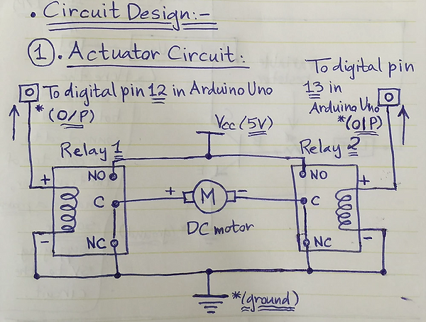
In this first step, we come up with the idea of our circuit design by simply free-hand sketching our circuit along with all the required components that we will be using and the necessary connections between them. In the two figures below you can see both theactuator and control circuits respectively, where the actuator circuit shows the connections between the DC motor, the two relays that act as an H-bridge (motor driver), and the digital pins of the Arduino Uno that we will be using. While the control circuit shows the connections between the Light Dependent Resistor "LDR" (which we use as a sensor), the potentiometer/ variable resistor, the transistor switch, and the digital pins of the Arduino Uno. Of course, both the actuator and control circuits are connected together in the real hardware via the Arduino Uno board to form one circuit as noted in the second figure of the control circuit. The circuit connections will be discussed in more details later in this section.

Here is a table showing all the required components along with their functions and the quantity of each component that we used.

And here is also a detailed bulleted list of all the connections for each component in the circuit.
Connections:
-
LDR Sensor: has two terminals, one is connected to the Vcc (5V) while the other is connected to the transistor's base.
-
Transistor BC547: has three legs (C - B - E), the collector (C) to which the load is connected, which in this case is the Arduino, so it connects to digital input pin 11 of the Arduino to provide the input signal originally coming from the LDR sensor, the base (B) is connected to both the LDR sensor and the potentiometer, and the emitter(E) is directly connected to the ground.
-
Potentiometer B10k: also has three legs, one of the side legs is connected to the transistor's base and the middle leg is directly connected to the ground.
-
3V LED: has two terminals (anode and cathode), the anode (+ve/ longer leg) is connected to the Vcc (5V) and the cathode (-ve/ shorter leg) is connected to the transistor's collector.
-
Relays: we have two of them and each has five legs (NO - NC - C - coil end 1- coil end 2), the normally open (NO) switch legs in the two relays are both connected to each other with a common junction/ node connected to the Vcc (5V), the normally closed(NC) switch legs in the two relays are also both connected to each other but with a common junction/ node connected to the ground, the common (C) legs in both relays are connected to the two motor terminals, the first coil end (coil end 1) is connected directly to the ground in both relays, and finally the second coil end (coil end 2) in both relays is each connected to a different digital output pin in the Arduino where one is connected to digital pin 12 and the other to digital pin 13. (Note: There must be a potential difference between the two ends of a relay's coil so that current would flow in the coil magnetizing it in order for the relay to latch properly.)
-
Arduino Uno Board: as discussed in the transistor switch and relays connections, where we showed how digital I/P pin 11 and both digital O/P pins 12 and 13 are respectively connected. Also, the 5V pin in Arduino is connected to the positive Vcc line of the breadboard and the GND pin in Arduino is connected to the negative ground line of the board to close the circuit. And finally, the Arduino board itself is connected to the PC via a USB cable, which is from where the Arduino gets power and also in order to be able to upload/ burn our code on the Arduino Atmega328P which will be highlighted more in the following section.
b) Designing logic flowchart and writing Arduino code:In this second step, we work on the logic of the code by first drawing a flowchart that describes the idea and logical sequence of our code as shown in the figure below. We draw our flowchart on a website that is very useful and efficient in drawing flowchart diagrams and various other types of diagrams. (Link here: https://driver.draw.io)
_JPG.jpg)
As shown above, we first start designing the flowchart by drawing a circular "Start" node at the very top to indicate the start of the process/ code, then we draw a square indicating the "process" of defining our variables which include: a count variable (C) that counts how many times we press on the LDR sensor, a flag variable (F) that indicates the previous state of the LDR whether it was pressed before or not, a sensor value variable (SV) that stores the input value from the LDR coming from digital input pin 11 in the Arduino to indicate whether the LDR is currently pressed or not, and the output variables (r1 and r2) that give out the output values on digital output pins 12 and 13 in the Arduino which are then passed to the relays to operate the motor (Note: All the variables are initially equal to zero and the output variables are initially Low as the motor is not working at first). Then, we make a parallelogram shape indicating that we are reading an "input" from the LDR sensor and store this input's value in the sensor value variable in the following square shaped "process". The rest of the code's logical sequence and if conditions are described in further details in a screenshot of the Arduino code using comments that will be shown later in this section. (Note: This flowchart has no "End" node as the process keeps repeating and the code runs in an infinite loop in Arduino)
Remarks on drawing flowcharts:
-
The "Start"and "End" of a particular process/ code are drawn in a circular or oval shape.
-
Any "process" or "operation" is drawn in a square shape.
-
Any "input" or "output" is drawn in a parallelogram shape.
-
Any "condition" or "decision" is drawn in a diamond shape.
After describing the idea and logical sequence of the code using a flowchart, it was time to write the Arduino code. But first, you need to install Arduino program on your device. We will go through all the steps required to install Arduino and the steps we went through to write and upload our code which include:
1. Go to Arduino's website. (Website's Link: https://www.arduino.cc/)
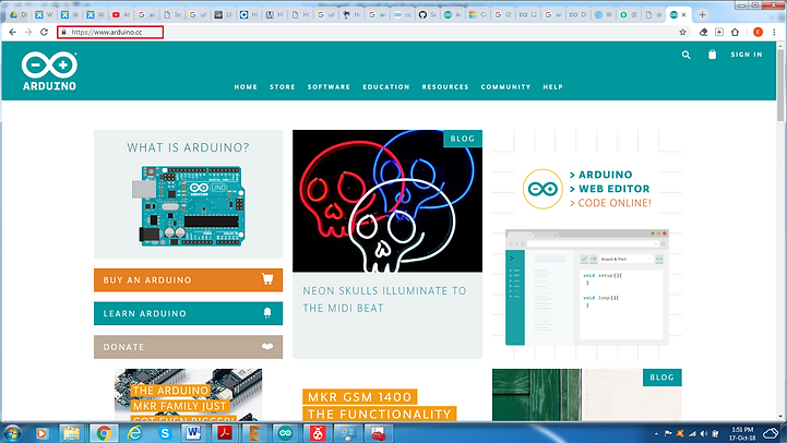
2. To download the latest version of Arduino's software, select "SOFTWARE" and then choose "DOWNLOADS" as shown in the figure below.

3. Now, you will get directed to the software page, go to "Download the Arduino IDE". You can download the software for Windows, Mac OS X, or Linux, so choose your operating system and click on it. Then, you will get directed to another page where you press "JUST DOWNLOAD" as shown in the following figures.


4. After downloading and installing the program on your PC, open "Arduino" and the GUI for a new Sketch appears as shown in the figures below.

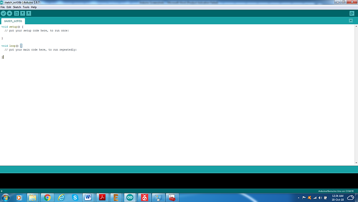
5. Now, we write our code in the sketch above along with all the associated comments, as shown in the figures below, that explain exactly the code structure and how the code's logic works.
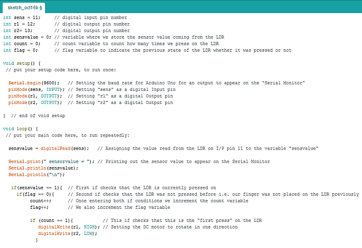

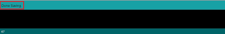
6. Save the code sketch by going to "File", select "Save", choose the directory that you want to save in and choose a file name, then press Save as shown in the figures below. (Note:Make sure that a "Done Saving." message appears near the bottom of the sketch's GUI as shown in the third figure.)


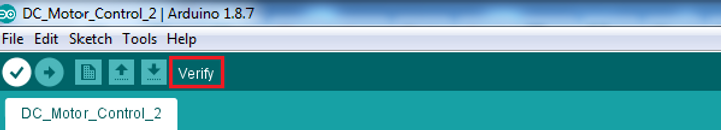
7. Now, it is time to compile/ verify the code to check for any errors that might be present. We go to the circular icon containing a check mark that is found in the toolbar at the top and click on it as shown in the first figure. The code begins compiling as shown in the second figure. And finally, make sure that this time a "Done compiling." message appears near the bottom of the sketch's GUI as shown in the third figure. (Note: If there is any syntax/ compilation error present it should appear in the black layout at the bottom and it will usually be written in an orange color and indicating the exact line of code where the error exists.)


8. Finally, comes the time to upload our code into the Arduino Uno board so we connect the board to the PC using the USB cable and make sure that the computer reads the Arduino on a certain COM port. Then, we head to "Tools" to configure the board type that we are using along with the COM port that the Arduino is connected to, so in Tools we go to "Board:" and choose the board type to be "Arduino/ Genuino Uno" and at the same time we select the port to which the Arduino Uno is connected by going to "Port" and selecting the COM port as shown in the first and second figures respectively. To upload the code, we go to the circular icon containing a right arrow mark that is found in the toolbar at the top, directly to the right of the verify icon, and click on it as shown in the third figure. Again, make sure that a "Done uploading." message appears near the bottom of the sketch's GUI, as shown in the forth figure, to ensure that your code has been successfully uploaded on the Atmega chip. To see an output on the serial monitor, we also go to "Tools" and choose "Serial Monitor" as indicated in the fifth figure.


9. Here is the output that appears when opening the serial monitor, the sensor value is equal to 0 when the LDR is not pressed and equal to 1 when pressed as shown in the figure below.
c) Making the circuit design and simulating it on Tinkercad:
In this third step, we run a software simulation of our circuit, but in order to run the simulation we first needed to make the circuit design and write the Arduino code which we already did in the previous two steps. We design the circuit and run the simulation on a program called "Tinkercad".
So, what is Tinkercad?
Autodesk's Tinkercad is one of the most popular classroom tools for creating simple designs from scratch, quickly modifying existing designs. It’s a free online 3D design program that you can use in your web browser without downloading any software. Tinkercad is extremely intuitive and easy to use, and has built-in Lessons to help you learn the ropes, making it perfect for beginners both young and old. It excels at cutting things into parts, adding simple features, making holes, and combining, aligning, and arranging objects. It’s easy to bring existing designs into Tinkercad to make quick modifications or additions, so advanced designers can also benefit by including Tinkercad in their design toolbox. You can import 3D STL models into Tinkercad for modifying or incorporating into other models, or import 2D SVG images that can be used to make extruded patterns, lettering, and designs. When you’re done designing you can export to STL for 3D printing, or even directly to Thingiverse, Shapeways, or Minecraft.
Tinkercad also recently added Tinkercad Circuits which help you bring your 3D designs to life with circuits assemblies, design integrated products, program and simulate your designs including: real time simulations, Arduino programming, and many starter circuits examples.
After introducing what is Tinkercad, we will now go through the detailed steps of working on it which include:
1. Go to Tinkercad's website. (Website's Link: https://www.tinkercad.com/#/)

2. If you don’t already have a Tinkercad account, then create one as shown in the figure below. I already had an account, so I signed in.

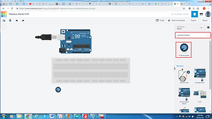
3. Go to Tinkercad "Circuits" by clicking on Circuits to switch from 3D Designs to Circuits mode, then click on "Create new Circuit" as shown in the figure below. If everything is all right let's start working and discover this platform.

4. Start searching for the circuit components by typing in their names in the "Search" bar located at the far right, then drag and drop them into the work space as shown in the figures below. (Note: Regarding the two relays, the relays found in Tinkercad's library were a different type from the relays that we used in the hardware having six legs instead of five, so I couldn't figure out their exact connections and had to exchange them with another component that does their same function, acting as an H-bridge, which is the motor driver"L293D").


5. Make all the required connections between the components, discussed above, using the breadboard as shown in the figure below. The connections required for the motor driver L293D can be viewed through this link. (Link: https://www.engineersgarage.com/electronic-components/l293d-motor-driver-ic)
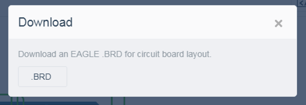
6. Once done with connecting our circuit, we export it as a board (".BRD" extension) to the program "EAGLE" by clicking the "Export" button at the top right corner and downloading it, then the circuit opens up in EAGLE as shown in the figures below.


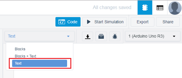
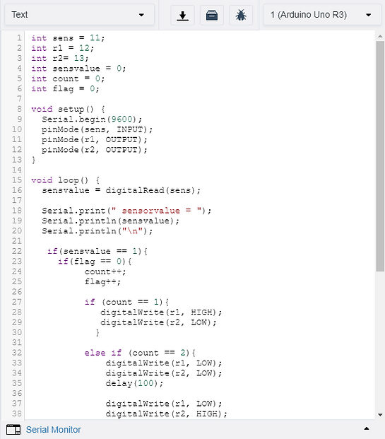
7. Afterwards, we start inserting our Arduino code, that we wrote in the previous step, by clicking the "Code" button in the top toolbar, choosing "Text" as we are inserting a text code and not a block code which is the default for Tinkercad, then copying and pasting our code from Arduino and make sure the Arduino board selected is "Arduino Uno R3" as shown in the figures below. We can also show the serial monitor at the bottom to view the output as shown below.


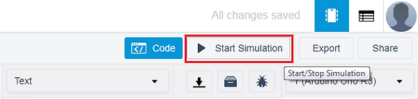
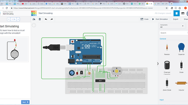
8. Now, it is time to run the simulation by clicking the "Start Simulation" button in the top toolbar, directly to the right of the "Code" button, as shown in the following figure.

And here is a video we recordedto explain how we made our circuit design and simulation on Tinkercad.
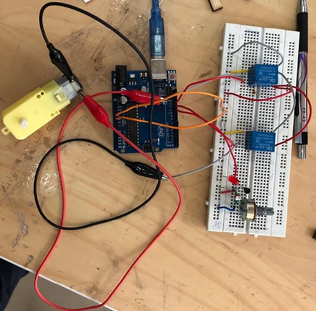
d) Implementing the circuit in hardware:
Our final step was to implement the circuit in hardware, as shown in the figure below, and connect the Arduino Uno board to the PC to run our code and ensure that all the hardware is functioning properly.
Finally, here is a video of the same circuit and motor but with an additional 3D printed fan attached to the motor shaft that we made as an extra bonus to integrate between 3D printing, electronics, and programming as well. :D
Conclusion
In summary, this task was very informative and interesting as we got to integrate between both electronics and programming and understand their fundamentals through practical work.